Comparison UNI-T UT213C vs UNI-T UT10A
Add to comparison | 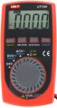 | |
|---|---|---|
| UNI-T UT213C | UNI-T UT10A | |
from $72.00 | from $29.60 up to $32.40 | |
| TOP sellers | ||
| Product type | clamp meter | multimeter |
| Type | digital | digital |
Measurement types | ||
| Measurements | voltage current resistance capacity temperature frequency duty cycle | voltage resistance capacity frequency duty cycle |
Specs | ||
| Current type | AC / DC | |
| Voltage type | AC / DC | AC / DC |
| DC voltage minimum | 400 mV | 400 mV |
| DC voltage max. | 600 В | 500 В |
| Measurement accuracy (V⁻) | 0.8 % | |
| AC voltage minimum | 4000 mV | 4000 mV |
| AC voltage max. | 600 В | 500 В |
| DC max. | 400 А | |
| AC max. | 400 А | |
| Impedance minimum | 400 Ω | 400 Ω |
| Impedance max. | 40 MΩ | 4 MΩ |
| Display count | 3999 | 3999 |
| Display value | 3 3/4 | 3 3/4 |
Features | ||
| Functions | diode test continuity test mode NCV (non-contact voltage) True RMS autoranging | transistor test diode test continuity test mode autoranging |
| In box | battery test probes case (bag) | battery test probes case (bag) |
General | ||
| Display backlight | ||
| Fixed probes | ||
| Power source | battery | battery |
| Battery type | 3xAAA | 1xCR2032 |
| Dimensions | 220x75x40 mm | 108x58x12 mm |
| Weight | 280 g | 120 g |
| Added to E-Catalog | october 2016 | october 2016 |
Compare UNI-T UT213C and UT10A
You may be interested in
UNI-T UT213C often compared


UNI-T UT10A often compared

Glossary
Product type
— Voltmeter. Electrical voltage is measured in volts; accordingly, devices of this type are designed primarily to measure voltage, and most often - only for this and nothing more. However, in addition to voltage, in practice one often has to deal with many other parameters, and modern technologies make it possible to create compact, functional and at the same time inexpensive universal devices. Therefore, voltmeters in their pure form are found and used relatively rarely, and most users dealing with electrical engineering prefer to use multimeters (see below).
— Multimeter. Devices of this type are also colloquially called "testers". A multimeter is a multi-purpose measuring instrument that combines the functions of at least a voltmeter, ammeter and ohmmeter - that is, it can measure voltage, power and resistance. In addition, other functions may be provided - for example, measuring capacitance, inductance, temperature (see “Functions”). For measurements, as a rule, a pair of probes is used. Due to their versatility combined with a relatively low cost, multimeters are the most popular type of measuring instruments; they can be used both for simple tasks such as checking radio components or household networks, and for working with complex circuits.
— Current clamps. Initially, such clamps are specific devices that allow you to measure power strength in...a non-contact manner, without touching the wires or interfering with the operation of the circuit. They operate as follows: the clamps cover the wire and, due to the characteristics of the magnetic field around it, measure the power strength. Both AC and DC power can be measured this way (though specific capabilities will, of course, vary by model). In addition to measurements without breaking the circuit, the advantage of clamps is the ability to work with high currents and voltages - hundreds of amperes in networks of hundreds of volts; Moreover, the measurements themselves are safer than with the usual contact method. On the other hand, the measurement accuracy is relatively low - usually no higher than class 2.5. In addition, the reliability of the result strongly depends on the correct position of the clamps, and with alternating power, also on the uniformity of the sinusoid (however, in advanced models special circuits may be provided to compensate for this dependence). In addition, non-contact measurement is not always practically applicable. Current clamp meters can be made in the form of a specialized device, but most often devices of this type are made in the form of multimeters, supplemented with a magnetic circuit for non-contact measurements and also capable of working using the usual contact method.
- Oscilloscope. Oscilloscopes are instruments designed to observe, measure and record electrical signal parameters. A distinctive feature of a classic oscilloscope is the screen on which the device builds a graph of the signal supplied to the input. Simultaneous operation with several signals can be supported (for more details, see “Number of channels”). However, some models do not have their own screen and are connected to a computer for measurements (see “USB oscilloscope”). Many signal parameters can be determined from its graph - this graph is usually supplemented by a coordinate scale that clearly illustrates frequency, amplitude, etc.; however, the oscilloscope can also display some parameters, such as phase angle, as specific numerical data. Modern oscilloscopes are capable of operating with frequencies up to gigahertz inclusive and most often use digital circuits (see “Type”), which makes them superior in accuracy to classic analog instruments.
- Skopmeter. Universal devices that combine both a multimeter and an oscilloscope in one housing. Both of these types are described in more detail above; Let us note here that such a combination provides very extensive functionality, however, scope meters are not cheap, and their measurement accuracy is lower than that of specialized multimeters and/or oscilloscopes.
— Insulation tester (megaohmmeter). Instruments that can be used to check the quality of insulation. For such a test, it is enough to determine the electrical resistance of the insulation - however, it can be very high, millions of ohms or even more. In light of this, the traditional measurement method - applying a low voltage to the material, determining the strength of the resulting power and calculating the resistance - is not suitable for insulation; special procedures are needed. Devices that provide such capabilities are called megohmmeters. They can support different insulation testing techniques; These methods are described in detail in special sources, and the features of specific devices are described in the manufacturer’s documentation. We only note that modern devices from this category are rarely made in the form of highly specialized devices - most often these are the same universal multimeters, supplemented with an insulation testing mode.
— Voltage tester. Portable pen-shaped testers for safely measuring voltage in an outlet or indicating the presence of power in wiring. The latter detect voltage in a non-contact manner, i.e. without having to touch the object. With their help, you can check the functionality of the outlet, detect the break point of the laid wiring or the point where the wire is broken. The voltage is determined by the tester at a distance of several centimeters, thereby preventing electric shock and other unpleasant consequences. Voltage meters usually operate on two “little finger” batteries (AAA type).
Measurements
The parameters that the device can measure.
— Tension. Voltage (potential difference between two points in a circuit), measured in volts. One of the basic electrical parameters, supported by all types of devices, except for oscilloscopes (see "Device"). Parallel connection is used for measurement. In analogue instruments (see "Type") voltage measurement can be carried out without power.
— Current. The strength of the current flowing through a certain section of the circuit; measured in amperes. There are two ways to measure current strength: traditional and non-contact. The first one is available in almost all devices with the ammeter function, for this it is necessary to open the circuit and connect the device to the gap in series (moreover, with the analogue principle of operation, the ammeter does not require power). The second method is used in current clamps (see "Device"). In most cases, the models are able to measure direct and alternating current.
— Impedance. Impedance of a certain element to direct electric current; measured in ohms. Note that in this case we are talking about traditional measurements that are not associated with ultra-high resistances characteristic of insulation (in insulation, this parameter is checked using a separate method, see more about it below...). Impedance measurements are carried out as follows: a certain voltage (low, within a few volts) is applied to the probes of the device, after which they are applied to the place of measurement — and the impedance of the tested section of the circuit or other object is calculated from the strength of the current flowing through the formed circuit. Thus, to operate in ohmmeter mode, a power source is required — even for an analogue instrument.
— Capacity. The capacitance of a capacitor is measured in farads (usually microfarads and other derived units). The measurement itself is carried out by supplying an alternating current to the capacitor. This function can be useful both for clarifying the capacitance of unmarked capacitors (initially unmarked or with erased inscriptions), and for checking the quality of signed parts. On capacitors, in addition to the nominal capacity, the maximum deviation from the nominal value may be indicated; if the measurement results are outside the tolerance limits, then it is better not to use the part. If the deviation is not indicated, then it can be assumed that it should be less than 10% of the nominal value. For example, for a 0.5 uF part, the range of allowable capacitances will be 0.45 – 0.55 uF.
— Temperature. Temperature measurement — usually, using an external remote sensor, usually on a probe. In electrical engineering, this function is used to control the operation of parts that are sensitive to overheating or that must operate in a certain temperature regime.
— Frequency. The ability to measure the frequency of an electrical signal is primarily characteristic of oscilloscopes and scopometers, but it can also be found in other types of devices — the same multimeters (see "Device"). This, usually, implies the ability to display specific numbers corresponding to the frequency in hertz.
— Duty cycle. Duty cycle is one of the basic characteristics of a uniform pulse signal, namely the ratio of its repetition period to the duration of a single pulse. For example, if each 2 ms pulse is followed by a 6 ms pause, then the signal repetition period will be T = 6 + 2 = 8 ms, and the duty cycle will be S = 8/2 = 4. Do not confuse the duty cycle with the duty cycle: although these characteristics describe the same property of the signal, they do it in different ways. The duty cycle is the reciprocal of the duty cycle, the ratio of the pulse length to the repetition period (in our example, it will be equal to 2/8 = 25%). This term is found mainly in English and translated sources, while in east european electrical engineering the term "duty cycle" is adopted.
— Inductance. Inductance is the main operating parameter of any inductor. The ability to measure this parameter is important in light of the fact that specialists and radio amateurs often make coils on their own, and it is extremely difficult, if not impossible, to determine the characteristics of a part without a special device. The principle of measuring inductance is similar to determining the capacitance of a capacitor (see above) — passing an alternating current through the coil and tracking its "response". However, this function is much less common than capacitance measurement.
— Insulation impedance. Insulation impedance of electrical wires to alternating current. Insulation, by definition, has an extremely high impedance, so the traditional way of measuring impedance (at low operating voltage, see above) is not applicable here — the currents would be too weak and it would be impossible to measure them accurately. Therefore, to check insulating materials and other dielectrics, not ohmmeters are used, but special devices — megaohmmeters (or multimeters that support this mode). A distinctive feature of the megohmmeter is a high operating voltage — hundreds or even thousands of volts. For example, to test insulation with an operating voltage of 500 V, the same megger voltage is required, for a 3000 V material, a 1000 V device, etc., the requirements for different types of insulation are described in more detail in special sources. To achieve this voltage, an external high-voltage module may be required, however, many multimeters that support this type of measurement are also capable of independently generating short-term high-voltage pulses from low-voltage power supplies such as AA batteries or PP3 (see "Battery type"). Note that when working with a megohmmeter, you must carefully follow the safety rules — due to the high operating voltage.
— Power. The power of the electric current is determined by two basic parameters — current strength and voltage; roughly speaking, volts must be multiplied by amps, the result obtained will be the power in watts. Thus, theoretically, this parameter can be determined without a special function for measuring power — it is enough to determine the voltage and current strength. However, some measuring instruments have a special mode that allows you to immediately measure both basic parameters and automatically calculate the power based on them — this is more convenient and faster than doing calculations separately. Many of these devices belong to current clamps (see "Device") and the measurement of the current strength when determining the power is carried out in a non-contact way, and the voltage is measured by the classic contact method. There are other design options — for example, an adapter for a socket: an electrical appliance is connected to a socket through such an adapter, and a multimeter takes current and voltage data from the adapter. We also recall that the active (useful) power of the alternating current is not always equal to the full one — with a capacitive and/or inductive load, part of the power (reactive power) is “consumed” by capacitors / coils. You can read more about these parameters in special sources, but here we note that different models of multimeters may have different capabilities for measuring different types of power; These points do not hurt to clarify before buying in advance.
— Phase angle. Measurement of the degree of shift of two electrical signals (or signal parameters) in phase. Specific types and features of such measurements are different, the most popular are two options. The first is to measure the difference between the phases of a three-phase power supply, primarily to assess its overall quality. The second is an assessment of the phase shift between current and voltage that occurs with a reactive (capacitive or inductive) load on an alternating current source; the ratio between active and apparent power (power factor, "cosine phi") directly depends on such a shift.
— Rotation frequency. In this case, most often we are talking about the possibility of measuring the speed of the internal combustion engine. Accordingly, such models usually refer to specialized automotive multimeters. They are designed mainly for diagnostics and testing of engines that do not have electronic ignition systems. To measure, usually, you need to set the multimeter to the number of engine cylinders and connect it to the ignition system (the specific connection method must be specified in the documentation for the car).
Note that this list does not list all, but only the most popular measurements found in modern multimeters and other devices of a similar purpose. In addition to them, the design may provide more specific features — see "Other Dimensions" for more details.
Current type
The type of current the device is designed to measure. In this case, not all measurement modes are implied, but only the determination of the current strength, that is, operation in the ammeter mode.
— Constant. A current that has a strictly defined polarity and constantly flows in one direction, from minus to plus. Such a current is found mainly in electronic circuits behind power supplies, in compact electronics powered by batteries, as well as in car on-board networks. However, during electrical work in domestic and industrial AC networks, it is relatively rare to measure the current strength; therefore, among such devices, there are often models that are compatible with "variable" networks in terms of voltage (see below), but not compatible in terms of current. In general, there are fewer DC-only devices on the market than combined ones (see below).
— Variable. A current that changes direction several dozen times per second (for example, in 230 V household networks, the standard frequency is 50 or 60 Hz, depending on the region). Such a current is a standard for domestic and industrial networks: it is convenient in that it does not require polarity when connecting end consumers, and it also provides some features that are not available for direct current (in particular, transformers can only be used with such a power supply). However, relatively few devices are produced strictly for alternating current, combined options are more common (see below).
...
— Constant / variable. This category includes models that can measure both direct and alternating current. The features of both options are described above, and their support in one device makes it universal and allows it to be used in any type of networks and circuits — the main thing is that the current limits are observed (see below).
DC voltage max.
The highest DC voltage (see “Voltage type”) that can be effectively measured with this instrument.
Compliance with this parameter is important not only for correct measurements, but also from a safety point of view. Measuring too high voltage can lead to malfunctions of the device, ranging from the operation of emergency protection (and it can take the form of a disposable fuse that requires replacement after operation) and ending with a complete failure and even fire. Therefore, it is impossible to exceed this indicator anyway. Yes, and choosing a device for maximum voltage is worth with a certain margin — at least 10 – 15%: this will give an additional guarantee in case of emergency situations. On the other hand, the margin should not be too large: a high constant voltage threshold can degrade the accuracy of measurements at low voltage, as well as affect the price, dimensions and weight of the device.
Note that most multimeters and other similar devices have several measurement ranges, with different maximum thresholds. So, for a safe measurement of voltage close to the maximum, you need to set the appropriate mode in the settings.
Measurement accuracy (V⁻)
Measurement accuracy provided by the instrument.
Measurement accuracy for multimeters is usually indicated by the smallest error (in percent) that the device is able to provide when measuring direct current. The smaller the number in this paragraph, the higher the accuracy, respectively. At the same time, we emphasize that it is the smallest error (the highest accuracy) that is usually achieved only in a certain measurement range; in other ranges, the accuracy may be lower. For example, if in the range "1 — 10 V" the device gives a maximum deviation of 0.5%, and in the range "10 — 50 V" — 1%, then 0.5% will be indicated in the characteristics. Nevertheless, according to this indicator, it is quite possible to evaluate and compare modern multimeters. So, a device with a lower claimed error, usually, and in general will be more accurate than a model with a similar performance with a larger error.
Data on measurement accuracy in other ranges and modes can be given in the detailed characteristics of the device. However, in fact, this information is required not so often — only for certain specific tasks, where it is fundamentally necessary to know the possible error.
AC voltage max.
The largest alternating voltage (see “Type of voltage”) that can be effectively measured using this model. This parameter is important not only for measurements as such, but also for safe handling of the device: measuring too high voltage will, at best, trigger emergency protection (and it is possible that after that you will have to look for a new fuse to replace the burned one), at worst — to equipment failure or even fire. In addition, for safe measurements, a voltage margin is highly desirable — this is due both to the characteristics of the alternating current and to the possibility of various emergency situations in the network, primarily voltage surges. For example, for 230 V networks, it is desirable to have a device for at least 250 V, and preferably 300 – 310 V; detailed recommendations for other cases can be found in special sources.
Note that most multimeters and other similar devices have several measurement ranges, with different maximum thresholds. So, for a safe measurement of voltage close to the maximum, you need to set the appropriate mode in the settings.
Note that most multimeters and other similar devices have several measurement ranges, with different maximum thresholds. So, for a safe measurement of voltage close to the maximum, you need to set the appropriate mode in the settings.
DC max.
The highest direct current (see “Type of current”) that the device is able to measure without overloads and related troubles (such as “flying” fuses or even failure).
When choosing for this parameter, it is worth remembering that even at relatively low voltages, the currents can be quite high if the power source provides the appropriate power — for example, a 12 V car battery is quite capable of delivering currents of hundreds of amperes. Actually, compatibility with high direct currents is important primarily for automotive devices; however, the matter is not limited to this.
For safe use, it is desirable to have a certain margin for maximum current. Also, do not forget that before measurements you need to set the appropriate settings.
AC max.
The largest alternating current (see "Type of current") that can be measured with this device. In no case should this parameter be exceeded — otherwise various troubles are possible, from the operation of the device's emergency protection (with further replacement of fuses) to fire.
When choosing for this parameter, it is worth remembering that even at relatively low voltages, the currents can be quite high if the power supply provides adequate power. For safe use, it is desirable to have a certain margin for maximum current. Also, do not forget that before measurements you need to set the appropriate settings.
When choosing for this parameter, it is worth remembering that even at relatively low voltages, the currents can be quite high if the power supply provides adequate power. For safe use, it is desirable to have a certain margin for maximum current. Also, do not forget that before measurements you need to set the appropriate settings.
Impedance max.
The highest resistance that the instrument can effectively measure.
When choosing according to this indicator, you must first take into account the largest resistances that are supposed to be measured. And if we are talking about an analogue device (see "Type"), you must also remember that as you approach the maximum resistance, the measurement accuracy drops sharply. This is due to the peculiarities of measuring and grading the scale in such devices: for example, with a maximum resistance of 1 MΩ, the division value in the range of 0 – 2 kΩ can be 0.2 kΩ, in the range of 2 – 6 kΩ — 0.5 kΩ, in the range of 6 – 10 kOhm — already 1 kOhm, and closer to the maximum this figure can reach tens and even hundreds of kilo-ohms. Therefore, it is worth choosing an analogue device in such a way that its maximum resistance is at least 10 times higher than the largest resistances that are planned to be measured — only under this condition is a more or less acceptable measurement accuracy ensured.
When choosing according to this indicator, you must first take into account the largest resistances that are supposed to be measured. And if we are talking about an analogue device (see "Type"), you must also remember that as you approach the maximum resistance, the measurement accuracy drops sharply. This is due to the peculiarities of measuring and grading the scale in such devices: for example, with a maximum resistance of 1 MΩ, the division value in the range of 0 – 2 kΩ can be 0.2 kΩ, in the range of 2 – 6 kΩ — 0.5 kΩ, in the range of 6 – 10 kOhm — already 1 kOhm, and closer to the maximum this figure can reach tens and even hundreds of kilo-ohms. Therefore, it is worth choosing an analogue device in such a way that its maximum resistance is at least 10 times higher than the largest resistances that are planned to be measured — only under this condition is a more or less acceptable measurement accuracy ensured.