
Comparison Gigabyte B650 EAGLE vs ASRock B650 PG Lightning
Add to comparison |  | 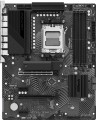 |
|---|---|---|
| Gigabyte B650 EAGLE | ASRock B650 PG Lightning | |
| Compare prices 1 | Compare prices 4 | |
| User reviews | ||
| TOP sellers | ||
Efficient cooling. M.2 with PCI Express 5.0 support. BIOS Flashback. USB-C connectors. Enhanced PCI. LSS support. | ||
| Features | gaming for overclocking | gaming for overclocking |
| Socket | AM5 | AM5 |
| Form factor | ATX | ATX |
| Power phases | 16 | 17 |
| VRM heatsink |  | |
| Size (HxW) | 305x244 mm | 305x244 mm |
Chipset | ||
| Chipset | AMD B650 | AMD B650 |
| BIOS | Ami | Ami |
| UEFI BIOS | | |
RAM | ||
| DDR5 | 4 slot(s) | 4 slot(s) |
| Memory module | DIMM | DIMM |
| Operation mode | 2 channel | 2 channel |
| Max. clock frequency | 7600 MHz | 7200 MHz |
| Max. memory | 192 GB | 192 GB |
| XMP | | |
| EXPO support | | |
Drive interface | ||
| SATA 3 (6Gbps) | 4 | 4 |
| M.2 connector | 3 | 3 |
| M.2 | 2xPCIe 4x, 1xPCIe 2x | 3xPCIe 4x |
| M.2 version | 1x5.0, 2x4.0 | |
| M.2 SSD cooling | | |
| Integrated RAID controller | | |
Expansion slots | ||
| 1x PCIe slots | 2 pcs | |
| PCIe 16x slots | 4 pcs | 2 pcs |
| PCIe modes | 16x/1x/1x/1x | 16x/2x |
| PCIe support | 4.0 | 4.0 |
| Steel PCIe connectors |  | |
Internal connections | ||
| TPM connector | | |
| USB-A 2.0 | 3 pcs | 2 pcs |
| USB-A 5Gbps | 1 pcs | 1 pcs |
| USB-C 5Gbps | 1 pcs | |
| USB-C 20Gbps | 1 pcs | |
| ARGB LED strip | 3 | 3 |
| RGB LED strip | 1 | 1 |
| More features | Q-Flash Plus button, Clear CMOS jumper | |
Video outputs | ||
| HDMI output | | |
| HDMI version | v2.1 | v2.1 |
| DisplayPort | | |
| DisplayPort version | v.1.4 | |
Integrated audio | ||
| Audiochip | Realtek | Realtek ALC897 |
| Sound (channels) | 7.1 | 7.1 |
Network interfaces | ||
| LAN (RJ-45) | 1 Gbps | 2.5 Gbps |
| LAN ports | 1 | 1 |
| LAN controller | Realtek | Dragon RTL8125BG |
External connections | ||
| USB-A 2.0 | 6 pcs | 4 pcs |
| USB-A 5Gbps | 7 pcs | |
| USB-A 10Gbps | 2 pcs | |
| USB-C 5Gbps | 1 pcs | |
| USB-C 20Gbps | 1 pcs | |
| PS/2 | 1 | |
| BIOS FlashBack | | |
Power connectors | ||
| Main power socket | 24-pin | 24-pin |
| CPU power | 8-pin | 8+8-pin |
| Fan power connectors | 5 | 6 |
| CPU Fan 4-pin | 1 | 1 |
| CPU/Water Pump Fan 4-pin | 1 | 1 |
| Chassis/Water Pump Fan 4-pin | 3 | 4 |
| Added to E-Catalog | june 2024 | october 2022 |



Compare Gigabyte B650 EAGLE and ASRock B650 PG Lightning
Price comparison
You may be interested in
My comparisons
ASRock B650 PG Lightning often compared


Glossary
Power phases
The number of processor power phases provided on the motherboard.
Very simplistically, phases can be described as electronic blocks of a special design, through which power is supplied to the processor. The task of such blocks is to optimize this power, in particular, to minimize power surges when the load on the processor changes. In general, the more phases, the lower the load on each of them, the more stable the power supply and the more durable the electronics of the board. And the more powerful the CPU and the more cores it has, the more phases it needs; this number increases even more if the processor is planned to be overclocked. For example, for a conventional quad-core chip, only four phases are often enough, and for an overclocked one, at least eight may be needed. It is because of this that powerful processors can have problems when used on inexpensive low-phase motherboards.
Detailed recommendations on choosing the number of phases for specific CPU series and models can be found in special sources (including the documentation for CPU itself). Here we note that with numerous phases on the motherboard (more than 8), some of them can be virtual. To do this, real electronic blocks are supplemented with doublers or even triplers, which, formally, increases the number of phases: for example, 12 claimed phases can represent 6 physical blocks with doublers. However, virtual phases are much inferior to real ones in terms of capabilities — in fact, t...hey are just additions that slightly improve the characteristics of real phases. So, let's say, in our example, it is more correct to speak not about twelve, but only about six (though improved) phases. These nuances must be specified when choosing a motherboard.
Very simplistically, phases can be described as electronic blocks of a special design, through which power is supplied to the processor. The task of such blocks is to optimize this power, in particular, to minimize power surges when the load on the processor changes. In general, the more phases, the lower the load on each of them, the more stable the power supply and the more durable the electronics of the board. And the more powerful the CPU and the more cores it has, the more phases it needs; this number increases even more if the processor is planned to be overclocked. For example, for a conventional quad-core chip, only four phases are often enough, and for an overclocked one, at least eight may be needed. It is because of this that powerful processors can have problems when used on inexpensive low-phase motherboards.
Detailed recommendations on choosing the number of phases for specific CPU series and models can be found in special sources (including the documentation for CPU itself). Here we note that with numerous phases on the motherboard (more than 8), some of them can be virtual. To do this, real electronic blocks are supplemented with doublers or even triplers, which, formally, increases the number of phases: for example, 12 claimed phases can represent 6 physical blocks with doublers. However, virtual phases are much inferior to real ones in terms of capabilities — in fact, t...hey are just additions that slightly improve the characteristics of real phases. So, let's say, in our example, it is more correct to speak not about twelve, but only about six (though improved) phases. These nuances must be specified when choosing a motherboard.
Max. clock frequency
The maximum RAM clock speed supported by the motherboard. The actual clock frequency of the installed RAM modules should not exceed this indicator — otherwise, malfunctions are possible, and the capabilities of the “RAM” cannot be used to the fullest.
For modern PCs, a RAM frequency of 1500 – 2000 MHz or less is considered very low, 2000 – 2500 MHz is modest, 2500 – 3000 MHz is average, 3000 – 3500 MHz is above average, and the most advanced boards can support frequencies of 3500 – 4000 MHz and even more than 4000 MHz.
For modern PCs, a RAM frequency of 1500 – 2000 MHz or less is considered very low, 2000 – 2500 MHz is modest, 2500 – 3000 MHz is average, 3000 – 3500 MHz is above average, and the most advanced boards can support frequencies of 3500 – 4000 MHz and even more than 4000 MHz.
M.2
Electrical (logical) interfaces implemented through physical M.2 connectors on the motherboard.
For more details about such connectors, see above. Here, we note that they can work with two types of interfaces:
For more details about such connectors, see above. Here, we note that they can work with two types of interfaces:
- SATA — a standard originally created for hard drives. Usually, the most recent version supported in M.2 is SATA 3; however, even it is significantly inferior to PCIe in terms of speed (600 MB/s) and functionality (only storage devices);
- PCIe — the most widespread modern interface for connecting internal peripherals (also known as NVMe). It is suitable for various expansion cards (such as wireless adapters) as well as storage devices, with PCIe speeds allowing for the full potential of modern SSDs to be realized. The maximum data transfer speed depends on the version of this interface and the number of lanes. In modern M.2 connectors, you can find PCIe versions 3.0 and 4.0, with speeds of approximately 1 GB/s and 2 GB/s per lane, respectively; and the number of lanes can be 1, 2, or 4 (PCIe 1x, 2x, and 4x, respectively)
M.2 version
The version of the M.2 interface determines both the maximum data transfer rate and the supported devices that can be connected via physical M.2 connectors (see the corresponding paragraph).
The version of the M.2 interface in the specifications of motherboards is usually indicated by the number of connectors themselves and by the PCIe revision provided for in each of them. For example, the entry “3x4.0” means three connectors capable of supporting PCIe 4.0; and the designation “2x5.0, 1x4.0” means a trio of connectors, two of which support PCIe 4.0, and another one supports PCIe 5.0.
The version of the M.2 interface in the specifications of motherboards is usually indicated by the number of connectors themselves and by the PCIe revision provided for in each of them. For example, the entry “3x4.0” means three connectors capable of supporting PCIe 4.0; and the designation “2x5.0, 1x4.0” means a trio of connectors, two of which support PCIe 4.0, and another one supports PCIe 5.0.
1x PCIe slots
The number of PCIe (PCI Express) 1x slots installed on the motherboard. There are motherboards with 1 PCIe 1x slot, 2 PCIe 1x connectors, 3 PCIe 1x ports, and even more.
The PCI Express bus is used to connect various expansion cards—network and sound cards, video adapters, TV tuners, and even SSDs. The number in the name indicates the number of PCIe lanes (data transmission channels) supported by this slot; the more lanes, the higher the bandwidth. Accordingly, PCIe 1x is the basic, slowest variety of this interface. The data transfer rate for such slots depends on the PCIe version (see "PCI Express Support"): specifically, it's just under 1 GB/s for version 3.0 and just under 2 GB/s for version 4.0.
It is worth noting that the general rule for PCIe is this: the card should be connected to a slot with the same or greater number of lanes. Thus, only single-lane cards will be guaranteed to be compatible with PCIe 1x.
The PCI Express bus is used to connect various expansion cards—network and sound cards, video adapters, TV tuners, and even SSDs. The number in the name indicates the number of PCIe lanes (data transmission channels) supported by this slot; the more lanes, the higher the bandwidth. Accordingly, PCIe 1x is the basic, slowest variety of this interface. The data transfer rate for such slots depends on the PCIe version (see "PCI Express Support"): specifically, it's just under 1 GB/s for version 3.0 and just under 2 GB/s for version 4.0.
It is worth noting that the general rule for PCIe is this: the card should be connected to a slot with the same or greater number of lanes. Thus, only single-lane cards will be guaranteed to be compatible with PCIe 1x.
PCIe 16x slots
Number of PCIe (PCI Express) 16x slots installed on the motherboard.
The PCI Express bus is used to connect various expansion cards — network and sound cards, video adapters, TV tuners, and even SSDs. The number in the name specifies the number of PCIe lanes (data transmission channels) supported by the slot; the more lanes, the higher the bandwidth. 16 lanes is the maximum number found in modern PCI Express slots and boards (technically more is possible, but the connectors would become too bulky). Accordingly, such slots are the fastest: they have a data transfer rate of 16 GB/s for PCIe 3.0 and 32 GB/s for PCIe 4.0 (see "PCI Express Support" for more details on versions).
It's worth noting that PCIe 16x is considered the optimal connector for connecting video cards. However, when choosing a motherboard with several such slots, it is important to consider the PCIe modes it supports (see below). Additionally, remember that the PCI Express interface allows connecting cards with fewer lanes to connectors with more lanes. Thus, PCIe 16x is suitable for any PCI Express card.
It is also worth mentioning that modern motherboards sometimes feature enlarged slots — in particular, PCIe 4x, which are the same size as PCIe 16x. However, the type of PCIe slots in our catalog is indicated by the actual bandwidth; thus, only connectors supporting speed at the 16x level are considered PCIe 16x.
The PCI Express bus is used to connect various expansion cards — network and sound cards, video adapters, TV tuners, and even SSDs. The number in the name specifies the number of PCIe lanes (data transmission channels) supported by the slot; the more lanes, the higher the bandwidth. 16 lanes is the maximum number found in modern PCI Express slots and boards (technically more is possible, but the connectors would become too bulky). Accordingly, such slots are the fastest: they have a data transfer rate of 16 GB/s for PCIe 3.0 and 32 GB/s for PCIe 4.0 (see "PCI Express Support" for more details on versions).
It's worth noting that PCIe 16x is considered the optimal connector for connecting video cards. However, when choosing a motherboard with several such slots, it is important to consider the PCIe modes it supports (see below). Additionally, remember that the PCI Express interface allows connecting cards with fewer lanes to connectors with more lanes. Thus, PCIe 16x is suitable for any PCI Express card.
It is also worth mentioning that modern motherboards sometimes feature enlarged slots — in particular, PCIe 4x, which are the same size as PCIe 16x. However, the type of PCIe slots in our catalog is indicated by the actual bandwidth; thus, only connectors supporting speed at the 16x level are considered PCIe 16x.
PCIe modes
Operating modes of PCIe 16x slots supported by the motherboard.
For more details about this interface, see above, and data on the modes is provided in case there are multiple PCIe 16x slots on the board. This data specifies the speed at which these slots can operate when expansion cards are simultaneously connected to them and how many lanes each can use. The fact is that the total number of PCI Express lanes on any motherboard is limited, and there are usually not enough for all 16-channel slots to operate at full capacity simultaneously. Accordingly, the speed inevitably has to be limited during simultaneous operation. For example, a 16x/4x/4x configuration means that the motherboard has three 16-channel slots, but if you connect three graphics cards to them simultaneously, the second and third slots can only provide speeds at the PCIe4x level. Accordingly, for a different number of slots, the quantity of digits will match. Some boards offer multiple mode variants, such as 16x/0x/4 and 8x/8x/4x (0x means the slot becomes unusable).
This parameter mainly needs attention when installing multiple graphics cards simultaneously: in some cases, (for example, when using SLI technology), for the adapters to work correctly, they must be connected to slots with the same speed.
For more details about this interface, see above, and data on the modes is provided in case there are multiple PCIe 16x slots on the board. This data specifies the speed at which these slots can operate when expansion cards are simultaneously connected to them and how many lanes each can use. The fact is that the total number of PCI Express lanes on any motherboard is limited, and there are usually not enough for all 16-channel slots to operate at full capacity simultaneously. Accordingly, the speed inevitably has to be limited during simultaneous operation. For example, a 16x/4x/4x configuration means that the motherboard has three 16-channel slots, but if you connect three graphics cards to them simultaneously, the second and third slots can only provide speeds at the PCIe4x level. Accordingly, for a different number of slots, the quantity of digits will match. Some boards offer multiple mode variants, such as 16x/0x/4 and 8x/8x/4x (0x means the slot becomes unusable).
This parameter mainly needs attention when installing multiple graphics cards simultaneously: in some cases, (for example, when using SLI technology), for the adapters to work correctly, they must be connected to slots with the same speed.
Steel PCIe connectors
The presence of reinforced steel PCIe connectors on the motherboard.
Such connectors are mainly found in gaming (see "By Direction") and other advanced types of motherboards designed for powerful graphics adapters. Typically, PCIe 16x slots are made of steel, specifically intended for such graphics cards; aside from the slot itself, the mounting to the board also features a reinforced design.
This feature offers two key advantages compared to traditional plastic connectors. Firstly, it allows for the installation of even large and heavy graphics cards with maximum reliability, without the risk of damaging the slot or the board. Secondly, the metal connector acts as a protective shield and reduces the likelihood of interference; this is especially useful when using multiple graphics cards installed side by side, "side-by-side."
Such connectors are mainly found in gaming (see "By Direction") and other advanced types of motherboards designed for powerful graphics adapters. Typically, PCIe 16x slots are made of steel, specifically intended for such graphics cards; aside from the slot itself, the mounting to the board also features a reinforced design.
This feature offers two key advantages compared to traditional plastic connectors. Firstly, it allows for the installation of even large and heavy graphics cards with maximum reliability, without the risk of damaging the slot or the board. Secondly, the metal connector acts as a protective shield and reduces the likelihood of interference; this is especially useful when using multiple graphics cards installed side by side, "side-by-side."
USB-A 2.0
The number of USB 2.0 connectors provided on the motherboard.
USB connectors (of all versions) are used to connect USB ports located on the front panel of the case to the "motherboard." A special cable connects such a port to the connector, with one connector typically working with just one port. In other words, the number of connectors on the motherboard corresponds to the maximum number of front-facing USB ports that can be used with it.
Specifically, USB-A 2.0 is the oldest version among those widely used today. It provides data transfer speeds up to 480 Mbps and is considered outdated, gradually being replaced by more advanced standards, primarily USB-A 5Gbps, 10Gbps. Nonetheless, quite a bit of peripheral equipment is still being produced for USB-A 2.0 ports: this interface's capabilities are quite sufficient for most devices that do not require high connection speeds.
USB connectors (of all versions) are used to connect USB ports located on the front panel of the case to the "motherboard." A special cable connects such a port to the connector, with one connector typically working with just one port. In other words, the number of connectors on the motherboard corresponds to the maximum number of front-facing USB ports that can be used with it.
Specifically, USB-A 2.0 is the oldest version among those widely used today. It provides data transfer speeds up to 480 Mbps and is considered outdated, gradually being replaced by more advanced standards, primarily USB-A 5Gbps, 10Gbps. Nonetheless, quite a bit of peripheral equipment is still being produced for USB-A 2.0 ports: this interface's capabilities are quite sufficient for most devices that do not require high connection speeds.