Air flow direction
The direction in which the active cooler (see "Type") airflow exits.
This parameter is relevant primarily for models used with processors, but the options can be as follows:
—
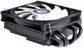
Sideways (scattering). Operation format typical for coolers of the so-called tower design. In these models, the fan is mounted perpendicular to the substrate in contact with the processor, due to which the airflow moves parallel to the motherboard. This ensures maximum efficiency: the heated air does not return to the processor and other system components, but is dissipated in the case (and almost immediately goes outside if the computer has at least one case fan). The main disadvantage of this option is the large height of the structure, which can make it difficult to place it in some system units. However, in most cases this point is not fundamental — especially when it comes to a powerful cooling system designed for an advanced system with a performant "hot" processor. So, it is side dissipation that is the most popular option nowadays — especially in coolers with a maximum TDP of 150 W and higher (although more modest models often use this layout).
—
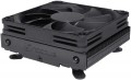
Down (to the motherboard). This format of operation allows you to "lay" the fan with a heatsink flat on the motherboard, significantly reducing the height of the entire cooler (compared to models using side blowing). On the other hand, this format of
...work is not very efficient — after all, before dissipating through the case, hot air again blows over the board with the processor. So nowadays, this option is relatively rare, and mainly in low-power coolers with an acceptable TDP of up to 150 W. And you should pay attention to such models mainly when there is little space in the case and a small cooler height is more important than high efficiency.Max. TDP
The maximum TDP provided by the cooling system. Note that this parameter is indicated only for solutions equipped with heatsinks (see "Type"); for separately made fans, the efficiency is determined by other parameters, primarily by the air flow values (see above).
TDP can be described as the amount of heat that a cooling system is able to remove from a serviced component. Accordingly, for the normal operation of the entire system, it is necessary that the TDP of the cooling system is not lower than the heat dissipation of this component (heat dissipation data is usually indicated in the detailed characteristics of the components). And it is best to select coolers with a power margin of at least 20 – 25% — this will give an additional guarantee in case of forced operation modes and emergency situations (including clogging of the case and reduced air exchange efficiency).
As for specific numbers, the most modest modern cooling systems provide TDP
up to 100 W, the most advanced —
up to 250 W and even
higher.
Bearing
The type of bearing used in the cooling fan(s).
The bearing is the piece between the rotating axle of the fan and the fixed base that supports the axle and reduces friction. The following types of bearings are found in modern fans:
—
Sliding. The action of these bearings is based on direct contact between two solid surfaces, carefully polished to reduce friction. Such devices are simple, reliable and durable, but their efficiency is rather low — rolling, and even more so the hydrodynamic and magnetic principle of operation (see below), provide much less friction.
—
Rolling. They are also called "ball bearings", since the "intermediaries" between the axis of rotation and the fixed base are balls (less often — cylindrical rollers) fixed in a special ring. When the axis rotates, such balls roll between it and the base, due to which the friction force is very low — noticeably lower than in plain bearings. On the other hand, the design turns out to be more expensive and complex, and in terms of reliability it is somewhat inferior to both the same plain bearings and more advanced hydrodynamic devices (see below). Therefore, although rolling bearings are quite widespread nowadays, however, in general, they are much less common than the mentioned varieties.
—
Hydrodynamic. Bearings of this type are filled with a special liquid; when rotate
...d, it creates a layer on which the moving part of the bearing slides. In this way, direct contact between hard surfaces is avoided and friction is significantly reduced compared to previous types. Also, these bearings are quiet and very reliable. Of their shortcomings, a relatively high cost can be noted, but in fact this moment often turns out to be invisible against the background of the price of the entire system. Therefore, this option is extremely popular nowadays, it can be found in cooling systems of all levels — from low-cost to advanced.
— Magnetic centering. Bearings based on the principle of magnetic levitation: the rotating axis is "suspended" in a magnetic field. Thus, it is possible (as in hydrodynamic ones) to avoid contact between solid surfaces and further reduce friction. Considered the most advanced type of bearings, they are reliable and quiet, but expensive.Min. RPM
The lowest speed at which the cooling fan is capable of operating. Specified only for models with speed control (see below).
The lower the minimum speed (with the same maximum) — the wider the speed control range and the more you can slow down the fan when high performance is not needed (such a slowdown allows you to reduce energy consumption and noise level). On the other hand, an extensive range affects the cost accordingly.
Max. air flow
The maximum airflow that a cooling fan can create; measured in CFM — cubic feet per minute.
The higher the CFM number, the more efficient the fan. On the other hand, high performance requires either a large diameter (which affects the size and cost) or high speed (which increases the noise and vibration levels). Therefore, when choosing, it makes sense not to chase the maximum air flow, but to use special formulas that allow you to calculate the required number of CFM depending on the type and power of the cooled component and other parameters. Such formulas can be found in special sources. As for specific numbers, in the most modest systems, the performance
does not exceed 30 CFM, and in the most powerful systems it can be up to 80 CFM and even
more.
It is also worth considering that the actual value of the air flow at the highest speed is usually lower than the claimed maximum; see Static Pressure for details.
MTBF
The total time that a cooling fan is guaranteed to run before it fails. Note that when this time is exhausted, the device will not necessarily break — many modern fans have a significant margin of safety and are able to work for some more period. At the same time, it is worth evaluating the overall durability of the cooling system according to this parameter.
Min noise level
The lowest noise level produced by the cooling system during operation.
This parameter is indicated only for those models that have capacity control and can operate at reduced power. Accordingly, the minimum noise level is the noise level in the most “quiet” mode, the volume of work, which this model cannot be less than.
These data will be useful, first of all, to those who are trying to reduce the noise level as much as possible and, as they say, “fight for every decibel”. However, it is worth noting here that in many models the minimum values are about 15 dB, and in the quietest — only 10 – 11 dB. This volume is comparable to the rustling of leaves and is practically lost against the background of ambient noise even in a residential area at night, not to mention louder conditions, and the difference between 11 and 18 dB in this case is not significant for human perception. A comparison table for sound starting from 20 dB is given in the "Noise level" section below.
Noise level
The standard noise level generated by the cooling system during operation. Usually, this paragraph indicates the maximum noise during normal operation, without overloads and other "extreme".
Note that the noise level is indicated in decibels, and this is a non-linear value. So it is easiest to evaluate the actual loudness using comparative tables. Here is a table for values found in modern cooling systems:
20 dB — barely audible sound (quiet whisper of a person at a distance of about 1 m, sound background in an open field outside the city in calm weather);
25 dB — very quiet (normal whisper at a distance of 1 m);
30 dB — quiet (wall clock). It is this noise that, according to sanitary standards, is the maximum allowable for constant sound sources at night (from 23.00 to 07.00). This means that if the computer is planned to sit at night, it is desirable that the volume of the cooling system does not exceed this value.
35 dB — conversation in an undertone, sound background in a quiet library;
40 dB — conversation, relatively quiet, but already in full voice. The maximum permissible noise level for residential premises in the daytime, from 7.00 to 23.00, according to sanitary standards. However, even the noisiest cooling systems usually do not reach this indicator, the maximum for such equipment is about 38 – 39 dB.
Heat pipes
Number of heat pipes in the cooling system
The heat pipe is a hermetically sealed structure containing a low-boiling liquid. When one end of the tube is heated, this liquid evaporates and condenses at the other end, thus removing heat from the heating source and transferring it to the cooler. Nowadays, such devices are widely used mainly in processor cooling systems (see "Intended use") — they connect the substrate that is in direct contact with the CPU and the heatsink of the active cooler. Manufacturers select the number of tubes based on the overall performance of the cooler (see "Maximum TDP"); however, models with similar TDPs can still differ markedly in this parameter. In such cases, it is worth considering the following: increasing the number of heat pipes increases the efficiency of heat transfer, but also increases the dimensions, weight and cost of the entire structure.
As for the number, the simplest models provide
1 – 2 heat pipes, and in the most advanced and powerful processor systems, this number can be
7 or more.