Comparison UNI-T UT139C vs UNI-T UT61E
Add to comparison | 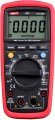 | 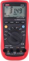 |
|---|---|---|
| UNI-T UT139C | UNI-T UT61E | |
from $35.70 | from $59.99 | |
| User reviews | ||
| TOP sellers | ||
| Product type | multimeter | multimeter |
| Type | digital | digital |
Measurement types | ||
| Measurements | voltage current resistance capacity temperature frequency duty cycle | voltage current resistance capacity frequency duty cycle |
Specs | ||
| Current type | AC / DC | AC / DC |
| Voltage type | AC / DC | AC / DC |
| DC voltage minimum | 60 mV | 220 mV |
| DC voltage max. | 600 В | 1000 В |
| Measurement accuracy (V⁻) | 0.5 % | 0.1 % |
| AC voltage minimum | 60 mV | 220 mV |
| AC voltage max. | 600 В | 750 В |
| DC minimum | 600 µA | 200 µA |
| DC max. | 10 А | 10 А |
| AC minimum | 600 µA | 200 µA |
| AC max. | 10 А | 10 А |
| Impedance minimum | 600 Ω | 220 Ω |
| Impedance max. | 60 MΩ | 220 MΩ |
| Display count | 5999 | 21999 |
| Display value | 3 5/6 | |
Features | ||
| Functions | diode test continuity test mode NCV (non-contact voltage) True RMS autoranging | diode test continuity test mode True RMS autoranging |
| In box | battery test probes | battery test probes data cable |
General | ||
| Display backlight | ||
| Stand | ||
| Power source | battery | battery |
| Battery type | 2xAA | PP3 |
| Dimensions | 175x81x48.5 mm | 180x87x47 mm |
| Weight | 370 g | 370 g |
| Added to E-Catalog | october 2016 | october 2016 |
Compare UNI-T UT139C and UT61E
You may be interested in
My comparisons
UNI-T UT139C often compared


UNI-T UT61E often compared


Glossary
Measurements
The parameters that the device can measure.
— Tension. Voltage (potential difference between two points in a circuit), measured in volts. One of the basic electrical parameters, supported by all types of devices, except for oscilloscopes (see "Device"). Parallel connection is used for measurement. In analogue instruments (see "Type") voltage measurement can be carried out without power.
— Current. The strength of the current flowing through a certain section of the circuit; measured in amperes. There are two ways to measure current strength: traditional and non-contact. The first one is available in almost all devices with the ammeter function, for this it is necessary to open the circuit and connect the device to the gap in series (moreover, with the analogue principle of operation, the ammeter does not require power). The second method is used in current clamps (see "Device"). In most cases, the models are able to measure direct and alternating current.
— Impedance. Impedance of a certain element to direct electric current; measured in ohms. Note that in this case we are talking about traditional measurements that are not associated with ultra-high resistances characteristic of insulation (in insulation, this parameter is checked using a separate method, see more about it below...). Impedance measurements are carried out as follows: a certain voltage (low, within a few volts) is applied to the probes of the device, after which they are applied to the place of measurement — and the impedance of the tested section of the circuit or other object is calculated from the strength of the current flowing through the formed circuit. Thus, to operate in ohmmeter mode, a power source is required — even for an analogue instrument.
— Capacity. The capacitance of a capacitor is measured in farads (usually microfarads and other derived units). The measurement itself is carried out by supplying an alternating current to the capacitor. This function can be useful both for clarifying the capacitance of unmarked capacitors (initially unmarked or with erased inscriptions), and for checking the quality of signed parts. On capacitors, in addition to the nominal capacity, the maximum deviation from the nominal value may be indicated; if the measurement results are outside the tolerance limits, then it is better not to use the part. If the deviation is not indicated, then it can be assumed that it should be less than 10% of the nominal value. For example, for a 0.5 uF part, the range of allowable capacitances will be 0.45 – 0.55 uF.
— Temperature. Temperature measurement — usually, using an external remote sensor, usually on a probe. In electrical engineering, this function is used to control the operation of parts that are sensitive to overheating or that must operate in a certain temperature regime.
— Frequency. The ability to measure the frequency of an electrical signal is primarily characteristic of oscilloscopes and scopometers, but it can also be found in other types of devices — the same multimeters (see "Device"). This, usually, implies the ability to display specific numbers corresponding to the frequency in hertz.
— Duty cycle. Duty cycle is one of the basic characteristics of a uniform pulse signal, namely the ratio of its repetition period to the duration of a single pulse. For example, if each 2 ms pulse is followed by a 6 ms pause, then the signal repetition period will be T = 6 + 2 = 8 ms, and the duty cycle will be S = 8/2 = 4. Do not confuse the duty cycle with the duty cycle: although these characteristics describe the same property of the signal, they do it in different ways. The duty cycle is the reciprocal of the duty cycle, the ratio of the pulse length to the repetition period (in our example, it will be equal to 2/8 = 25%). This term is found mainly in English and translated sources, while in east european electrical engineering the term "duty cycle" is adopted.
— Inductance. Inductance is the main operating parameter of any inductor. The ability to measure this parameter is important in light of the fact that specialists and radio amateurs often make coils on their own, and it is extremely difficult, if not impossible, to determine the characteristics of a part without a special device. The principle of measuring inductance is similar to determining the capacitance of a capacitor (see above) — passing an alternating current through the coil and tracking its "response". However, this function is much less common than capacitance measurement.
— Insulation impedance. Insulation impedance of electrical wires to alternating current. Insulation, by definition, has an extremely high impedance, so the traditional way of measuring impedance (at low operating voltage, see above) is not applicable here — the currents would be too weak and it would be impossible to measure them accurately. Therefore, to check insulating materials and other dielectrics, not ohmmeters are used, but special devices — megaohmmeters (or multimeters that support this mode). A distinctive feature of the megohmmeter is a high operating voltage — hundreds or even thousands of volts. For example, to test insulation with an operating voltage of 500 V, the same megger voltage is required, for a 3000 V material, a 1000 V device, etc., the requirements for different types of insulation are described in more detail in special sources. To achieve this voltage, an external high-voltage module may be required, however, many multimeters that support this type of measurement are also capable of independently generating short-term high-voltage pulses from low-voltage power supplies such as AA batteries or PP3 (see "Battery type"). Note that when working with a megohmmeter, you must carefully follow the safety rules — due to the high operating voltage.
— Power. The power of the electric current is determined by two basic parameters — current strength and voltage; roughly speaking, volts must be multiplied by amps, the result obtained will be the power in watts. Thus, theoretically, this parameter can be determined without a special function for measuring power — it is enough to determine the voltage and current strength. However, some measuring instruments have a special mode that allows you to immediately measure both basic parameters and automatically calculate the power based on them — this is more convenient and faster than doing calculations separately. Many of these devices belong to current clamps (see "Device") and the measurement of the current strength when determining the power is carried out in a non-contact way, and the voltage is measured by the classic contact method. There are other design options — for example, an adapter for a socket: an electrical appliance is connected to a socket through such an adapter, and a multimeter takes current and voltage data from the adapter. We also recall that the active (useful) power of the alternating current is not always equal to the full one — with a capacitive and/or inductive load, part of the power (reactive power) is “consumed” by capacitors / coils. You can read more about these parameters in special sources, but here we note that different models of multimeters may have different capabilities for measuring different types of power; These points do not hurt to clarify before buying in advance.
— Phase angle. Measurement of the degree of shift of two electrical signals (or signal parameters) in phase. Specific types and features of such measurements are different, the most popular are two options. The first is to measure the difference between the phases of a three-phase power supply, primarily to assess its overall quality. The second is an assessment of the phase shift between current and voltage that occurs with a reactive (capacitive or inductive) load on an alternating current source; the ratio between active and apparent power (power factor, "cosine phi") directly depends on such a shift.
— Rotation frequency. In this case, most often we are talking about the possibility of measuring the speed of the internal combustion engine. Accordingly, such models usually refer to specialized automotive multimeters. They are designed mainly for diagnostics and testing of engines that do not have electronic ignition systems. To measure, usually, you need to set the multimeter to the number of engine cylinders and connect it to the ignition system (the specific connection method must be specified in the documentation for the car).
Note that this list does not list all, but only the most popular measurements found in modern multimeters and other devices of a similar purpose. In addition to them, the design may provide more specific features — see "Other Dimensions" for more details.
DC voltage minimum
The upper limit of the lower sub-range in which the device can measure DC voltage (see "Type of voltage").
The operating ranges of modern multimeters and other measuring instruments are usually divided into subranges. This is done for accuracy and convenience when measuring: for example, to assess the quality of AA batteries, you can set the subrange “up to 3 V” — this will give an accuracy of up to tenths, or even hundredths of a volt, unattainable when measuring with a higher threshold. The minimum constant voltage describes exactly the lower subrange, designed to measure the smallest voltage values: for example, if 2000 mV is indicated in this paragraph, this means that the lower subrange covers values \u200b\u200bup to 2000 mV (i.e. up to 2 V).
It is worth choosing according to this indicator taking into account the specifics of the planned application: for example, a device with low rates can be useful for delicate work, such as repairing computers or mobile phones, but for servicing the on-board electrical network of a car, especially high voltage sensitivity is not required.
DC voltage max.
The highest DC voltage (see “Voltage type”) that can be effectively measured with this instrument.
Compliance with this parameter is important not only for correct measurements, but also from a safety point of view. Measuring too high voltage can lead to malfunctions of the device, ranging from the operation of emergency protection (and it can take the form of a disposable fuse that requires replacement after operation) and ending with a complete failure and even fire. Therefore, it is impossible to exceed this indicator anyway. Yes, and choosing a device for maximum voltage is worth with a certain margin — at least 10 – 15%: this will give an additional guarantee in case of emergency situations. On the other hand, the margin should not be too large: a high constant voltage threshold can degrade the accuracy of measurements at low voltage, as well as affect the price, dimensions and weight of the device.
Note that most multimeters and other similar devices have several measurement ranges, with different maximum thresholds. So, for a safe measurement of voltage close to the maximum, you need to set the appropriate mode in the settings.
Measurement accuracy (V⁻)
Measurement accuracy provided by the instrument.
Measurement accuracy for multimeters is usually indicated by the smallest error (in percent) that the device is able to provide when measuring direct current. The smaller the number in this paragraph, the higher the accuracy, respectively. At the same time, we emphasize that it is the smallest error (the highest accuracy) that is usually achieved only in a certain measurement range; in other ranges, the accuracy may be lower. For example, if in the range "1 — 10 V" the device gives a maximum deviation of 0.5%, and in the range "10 — 50 V" — 1%, then 0.5% will be indicated in the characteristics. Nevertheless, according to this indicator, it is quite possible to evaluate and compare modern multimeters. So, a device with a lower claimed error, usually, and in general will be more accurate than a model with a similar performance with a larger error.
Data on measurement accuracy in other ranges and modes can be given in the detailed characteristics of the device. However, in fact, this information is required not so often — only for certain specific tasks, where it is fundamentally necessary to know the possible error.
AC voltage minimum
The upper limit of the lower sub-range in which the device can measure AC voltage (see "Type of voltage").
The operating ranges of modern multimeters and other measuring instruments are usually divided into subranges. This is done for accuracy and convenience in measurements: for example, to test a transformer that should output 6 V, it makes sense to set a subrange with an upper threshold of 10 V. This will ensure accuracy up to tenths of a volt, unattainable when measuring with a higher threshold. The minimum constant voltage describes exactly the lower subrange, designed to measure the smallest voltage values: for example, if 2000 mV is indicated in this paragraph, this means that the lower subrange covers values \u200b\u200bup to 2000 mV (i.e. up to 2 V).
If the device is purchased for measurements in stationary networks — household at 230 V or industrial at 400 V — you can ignore this parameter: usually, the minimum subranges are not used. But to work with power supplies, step-down transformers and various “thin” electronics served by low voltage alternating current, it makes sense to choose a model with a lower minimum voltage. This is connected not only with the measurement range: a low threshold, usually, indicates a good measurement accuracy at low voltages in general.
AC voltage max.
The largest alternating voltage (see “Type of voltage”) that can be effectively measured using this model. This parameter is important not only for measurements as such, but also for safe handling of the device: measuring too high voltage will, at best, trigger emergency protection (and it is possible that after that you will have to look for a new fuse to replace the burned one), at worst — to equipment failure or even fire. In addition, for safe measurements, a voltage margin is highly desirable — this is due both to the characteristics of the alternating current and to the possibility of various emergency situations in the network, primarily voltage surges. For example, for 230 V networks, it is desirable to have a device for at least 250 V, and preferably 300 – 310 V; detailed recommendations for other cases can be found in special sources.
Note that most multimeters and other similar devices have several measurement ranges, with different maximum thresholds. So, for a safe measurement of voltage close to the maximum, you need to set the appropriate mode in the settings.
Note that most multimeters and other similar devices have several measurement ranges, with different maximum thresholds. So, for a safe measurement of voltage close to the maximum, you need to set the appropriate mode in the settings.
DC minimum
The upper limit of the lower sub-range in which the device can measure direct current (see "Type of current").
The operating ranges of modern multimeters and other measuring instruments are usually divided into subranges. This is done for accuracy and convenience in measurements: the lower the subrange, the smaller values it covers, the higher the measurement accuracy at low current values. The minimum direct current describes exactly the lower range, designed for the weakest current values: for example, if the characteristics in this paragraph indicate 500 μA, this means that the lower subrange allows you to measure currents from 0 to 500 μA.
It is worth choosing according to this indicator taking into account the specifics of the planned application: for example, a device with low rates can be useful for delicate work, such as repairing computers or mobile phones, but for servicing the on-board electrical network of cars, especially old ones, especially high current sensitivity is not required.
AC minimum
The upper limit of the lower sub-range in which the device can measure alternating current (see "Type of current").
The operating ranges of modern multimeters and other measuring instruments are usually divided into subranges. This is done for accuracy and convenience in measurements: the lower the subrange, the smaller values it covers, the higher the measurement accuracy at low current values. The minimum alternating current describes exactly the lower range, designed for the weakest current values: for example, if the characteristics in this paragraph indicate 500 μA, this means that the lower subrange allows you to measure currents from 0 to 500 μA.
It is worth choosing according to this indicator taking into account the specifics of the planned application: for example, a device with low rates can be useful for delicate work, such as repairing computers or mobile phones, but especially high current sensitivity is not required for servicing household electrical networks.
Impedance minimum
The upper limit of the lower sub-range in which the device can measure resistance.
The operating ranges of modern multimeters and other measuring instruments are usually divided into subranges. This is done for accuracy and convenience in measurements: the lower the subrange, the smaller the values it covers, the higher the accuracy of measurements at low resistance values. The minimum resistance describes exactly the lower range, designed for the weakest current values: for example, if the characteristics in this paragraph indicate 500 Ohms, this means that the lower subrange allows you to measure resistance from 0 to 500 Ohms.
When choosing for this indicator, you need to consider how important it is for you to accurately measure small resistances. At the same time, we note that the 500 Ohms given in the example are a fairly good indicator, indicating a fairly solid resistance measurement accuracy; in relatively inexpensive multimeters, this indicator can be 2.5 or even 10 kΩ, which ensures accuracy at best up to several tens of ohms.