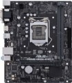
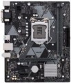
1x PCI-E slots
Number of PCI-E (PCI-Express) 1x slots installed on the motherboard. There are
motherboards for 1 PCI-E 1x slot,
2 PCI-E 1x slots,
3 PCI-E 1x ports and even more.
The PCI Express bus is used to connect various expansion cards — network and sound cards, video adapters, TV tuners and even SSD drives. The number in the name indicates the number of PCI-E lines (data transfer channels) supported by this slot; the more lines, the higher the throughput. Accordingly, PCI-E 1x is the basic, slowest version of this interface. The data transfer rate for such slots depends on the PCI-E version (see "PCI Express Support"): in particular, it is slightly less than 1 GB / s for version 3.0 and slightly less than 2 GB / s for 4.0.
Separately, we note that the general rule for PCI-E is as follows: the board must be connected to a slot with the same or more lines. Thus, only single-lane boards will be guaranteed to be compatible with PCI-E 1x.
HDMI output
The motherboard has its own
HDMI output.
Such an output is intended for transmitting video from an integrated graphics card (see above) or a processor with integrated graphics (we emphasize that it is impossible to output a signal from a discrete graphics card through the motherboard chipset). As for HDMI specifically, it is a combined digital video/audio interface specifically designed to work with HD resolutions and multi-channel audio. Today it is the most common of these interfaces, HDMI support is almost mandatory for video devices that are compatible with HD standards.
The specific capabilities of HDMI vary by version (see below for more details), but in general they are quite impressive — even in the earliest (current today) HDMI v.1.4, the maximum resolution is 4K, and in newer standards it reaches 10K. So in motherboards, the quality of the video transmitted through such an output is often limited not by the interface capabilities, but by the graphics performance of the system.
CPU Fan 4-pin
A four-pin connector used to connect a processor cooling fan. The first contact in it corresponds to the black wire of the cooler — it is the "ground" or minus of the power supply. The second contact is the plus of the power supply (yellow or red cooler wire). The third one is involved in measuring the rotation speed of the impeller (green or yellow fan wire). The fourth pin, corresponding to the blue wire, receives control signals from the PWM controller to adjust the cooler rotation speed depending on the temperature of the processor.
Chassis/Water Pump Fan 4-pin
A connector responsible for connecting additional coolers for the benefit of better cooling of components inside the system unit. Most often it is located on the edges of the motherboard — closer to the front side and the ceiling of the "system unit". It is made according to the four-contact scheme.

