
Comparison Novatek-Electro RN-101M1 vs Novatek-Electro RN-122
Add to comparison | 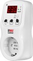 | 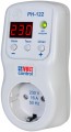 |
|---|---|---|
| Novatek-Electro RN-101M1 | Novatek-Electro RN-122 | |
| Outdated Product | Outdated Product | |
| TOP sellers | ||
| Device | voltage Monitoring Relays | voltage Monitoring Relays |
| Voltage | variable | variable |
| Number of phases | 1 | 1 |
| Mount | into socket | into socket |
Specs | ||
| Power | 3.5 kVA | 3.6 kVA |
| Maximum current | 16 А | 16 А |
| Voltage measuring range | 100 – 450 В | 120 – 400 В |
| Measurement accuracy (±) | 2 % | 1.3 % |
| Cut-off time (lower limit) | 0.12 с | 0.12 с |
| Off time (upper limit) | 0.05 с | 0.02 с |
| Reclosing delay | 5 – 900 с | 5 – 900 с |
| Lower cut-off limit | 160 – 230 В | 160 – 210 В |
| Upper cut-off limit | 240 – 290 В | 230 – 290 В |
| Functions | display operation indicator | display operation indicator |
General | ||
| Adjustment | mechanical | digital |
| Protection level | IP30 | IP30 |
| Dimensions | 76x122x61 mm | 61x122x76 mm |
| Weight | 200 g | 160 g |
| Added to E-Catalog | august 2022 | december 2017 |


Compare Novatek-Electro RN-101M1 and RN-122
You may be interested in
My comparisons
Novatek-Electro RN-101M1 often compared

Novatek-Electro RN-122 often compared


Glossary
Power
The rated power of the relay in kilovolt-amperes, in other words, the maximum apparent load power with which the device can normally operate.
From a physical point of view, kilovolt-amperes and kilowatts mean the same thing, but in kW it is customary to indicate only the active power of the load (see below), and in kVA — full. In AC networks, these powers can vary because active power (the power consumed by resistive-type devices such as heaters) is added to reactive power (the power consumed by capacitors and inductors). The apparent power is calculated from these two quantities.
When selecting control relays for AC networks, it is best to take into account the full power, especially if you plan to connect equipment with electric motors to the device. However, for many modern household appliances, only active power is given in the characteristics — in kilowatts. There are calculation methods that allow converting active power into total power, depending on the type and characteristics of the load; such techniques can be found in special sources.
From a physical point of view, kilovolt-amperes and kilowatts mean the same thing, but in kW it is customary to indicate only the active power of the load (see below), and in kVA — full. In AC networks, these powers can vary because active power (the power consumed by resistive-type devices such as heaters) is added to reactive power (the power consumed by capacitors and inductors). The apparent power is calculated from these two quantities.
When selecting control relays for AC networks, it is best to take into account the full power, especially if you plan to connect equipment with electric motors to the device. However, for many modern household appliances, only active power is given in the characteristics — in kilowatts. There are calculation methods that allow converting active power into total power, depending on the type and characteristics of the load; such techniques can be found in special sources.
Voltage measuring range
Voltage measurement range supported by the device.
Many modern control relays are equipped with digital displays, which can display, including current voltage; this parameter specifies the operating range of the built-in voltmeter. In this case, the voltage measurement range can be noticeably wider than the difference between the smallest minimum and the largest maximum shutdown threshold (see below). This allows you to use the relay also for online diagnostics of the network status.
For a current relay (see "Device") in this case, the range of operating voltages can be given directly — the voltage at which the device can normally perform its functions.
Many modern control relays are equipped with digital displays, which can display, including current voltage; this parameter specifies the operating range of the built-in voltmeter. In this case, the voltage measurement range can be noticeably wider than the difference between the smallest minimum and the largest maximum shutdown threshold (see below). This allows you to use the relay also for online diagnostics of the network status.
For a current relay (see "Device") in this case, the range of operating voltages can be given directly — the voltage at which the device can normally perform its functions.
Measurement accuracy (±)
Measurement accuracy provided by the device. In this case, different types of measurements may be implied, depending on the purpose of the relay (see "Device"). Note that in power relays and multifunctional devices, the measurement accuracy for voltage and current is usually the same, and a common parameter is given in the characteristics for them.
Accuracy is indicated by the maximum measurement error provided by the device. First of all, the operation accuracy depends on this parameter: the lower the error, the smaller the actual deviations from the specified operation parameters. For modern control relays, an indicator of 3 – 5% is considered acceptable, 1.5 – 3% is not bad, 1 – 1.5% is good, less than 1% is excellent. However, in fact, it is also worth choosing according to this parameter, taking into account how sensitive the connected load is to the accuracy of the specified operation parameters.
Also note that many modern relays are equipped with digital displays that can display various parameters. In such models, the measurement accuracy also determines the accuracy of the readings of such a built-in "tester".
Accuracy is indicated by the maximum measurement error provided by the device. First of all, the operation accuracy depends on this parameter: the lower the error, the smaller the actual deviations from the specified operation parameters. For modern control relays, an indicator of 3 – 5% is considered acceptable, 1.5 – 3% is not bad, 1 – 1.5% is good, less than 1% is excellent. However, in fact, it is also worth choosing according to this parameter, taking into account how sensitive the connected load is to the accuracy of the specified operation parameters.
Also note that many modern relays are equipped with digital displays that can display various parameters. In such models, the measurement accuracy also determines the accuracy of the readings of such a built-in "tester".
Off time (upper limit)
The device shutdown time on the upper limit of voltage or current. This is a kind of "reaction time" of the relay: the period of time between reaching the upper limit and turning off the protected network segment.
The lower this value, the more advanced the protection will be, the lower the probability of failure of sensitive devices due to untimely operation of the relay. Note that a short reaction time in this case is especially important, because too high a voltage or current is a serious danger to any device.
The lower this value, the more advanced the protection will be, the lower the probability of failure of sensitive devices due to untimely operation of the relay. Note that a short reaction time in this case is especially important, because too high a voltage or current is a serious danger to any device.
Lower cut-off limit
The lower voltage shutdown limit provided in the relay; when the voltage drops below this value, the device turns off the power to the protected network segment. Usually, this limit can be adjusted, and the specifications indicate the range of such adjustment.
Although the main danger for various electrical appliances is increased voltage, many devices do not tolerate too low voltage. Therefore, modern voltage relays provide shutdown not only on the upper, but also on the lower threshold.
Although the main danger for various electrical appliances is increased voltage, many devices do not tolerate too low voltage. Therefore, modern voltage relays provide shutdown not only on the upper, but also on the lower threshold.
Upper cut-off limit
The upper voltage shutdown limit provided in the relay is the voltage, when exceeded, the device turns off the power to the protected network segment. Usually, this limit can be adjusted, and the specifications indicate the range of such adjustment.
Adjustment
The method of managing the operating parameters provided in the device.
— Mechanical. Adjustment of parameters using mechanical switches, usually rotary, with scales printed next to them. In some models, these switches are manually adjusted, in others they must be turned with a screwdriver or other similar device. This method is simple, reliable and inexpensive, but not as convenient as digital adjustment, and has very low accuracy — for example, the re-closing time can be set with an accuracy of 20-30 seconds at best, and more often up to a minute or two.
— Digital. Adjustment of parameters using control electronic circuits. For such devices, it is mandatory to have a display: during adjustment, it displays a configurable parameter that can be changed by pressing the “+” (“Up”) and “—” (“Down”) buttons. Digital adjustment is somewhat more expensive than mechanical adjustment, but it significantly exceeds it in accuracy — the adjustment step can be 1 – 3 (seconds, volts, etc.).
— Mechanical. Adjustment of parameters using mechanical switches, usually rotary, with scales printed next to them. In some models, these switches are manually adjusted, in others they must be turned with a screwdriver or other similar device. This method is simple, reliable and inexpensive, but not as convenient as digital adjustment, and has very low accuracy — for example, the re-closing time can be set with an accuracy of 20-30 seconds at best, and more often up to a minute or two.
— Digital. Adjustment of parameters using control electronic circuits. For such devices, it is mandatory to have a display: during adjustment, it displays a configurable parameter that can be changed by pressing the “+” (“Up”) and “—” (“Down”) buttons. Digital adjustment is somewhat more expensive than mechanical adjustment, but it significantly exceeds it in accuracy — the adjustment step can be 1 – 3 (seconds, volts, etc.).