
Comparison Zubr MF2-40 red vs Zubr MF40
Add to comparison | 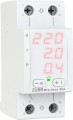 | 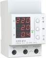 |
|---|---|---|
| Zubr MF2-40 red | Zubr MF40 | |
| Outdated Product | Outdated Product | |
| User reviews | ||
| TOP sellers | ||
| Device | voltage Monitoring Relays | multifunctional relay |
| Voltage | variable | variable |
| Number of phases | 1 | 1 |
| Mount | dIN rail | dIN rail |
| Width (unit) | 2 U | 3 U |
Specs | ||
| Power | 8.8 kVA | 8.8 kVA |
| Rated current | 40 А | 40 А |
| Maximum current | 50 А | 50 А |
| Voltage measuring range | 100 – 420 В | 100 – 420 В |
| Cut-off time (lower limit) | 0.03 с | 0.04 с |
| Off time (upper limit) | 0.03 с | 0.04 с |
| Response time adjustment |  |  |
| Reclosing delay | 3 – 999 с | 3 – 600 с |
| Lower cut-off limit | 120 – 210 В | 120 – 210 В |
| Upper cut-off limit | 220 – 280 В | 220 – 280 В |
| Current trip limit | 0.1 – 40 А | 0.1 – 40 А |
| Functions | display operation indicator thermal protection fault memory | display operation indicator thermal protection fault memory |
General | ||
| Adjustment | digital | digital |
| Protection level | IP20 | IP20 |
| Dimensions | 36x85x66 mm | 53x85x70 mm |
| Weight | 190 g | 210 g |
| Added to E-Catalog | november 2023 | october 2018 |


Compare Zubr MF2-40 red and MF40
You may be interested in
My comparisons
Zubr MF2-40 red often compared


Zubr MF40 often compared


Glossary
Device
— Voltage relay. Protective devices that automatically turn off the protected area when the mains voltage goes beyond the specified parameters. Usually, such devices are able to respond to both a significant increase and a significant decrease in voltage. A voltage relay will be a useful addition to traditional protection such as plugs or a circuit breaker, since such protection only reacts to excess current and does not monitor voltage. And in three-phase networks, protective relays can also provide monitoring of phase synchronization, triggering in case of skew, breakage, sticking or phase sequence violation.
— Current relay. Protective devices that automatically turn off the protected area when the consumed current exceeds the specified parameters. It is similar in purpose to circuit breakers, however, firstly, the current relays can also respond to a decrease in current, and secondly, such a device may not work instantly, but after a certain time. It makes sense to install a current relay where short-term operation at high currents is allowed, however, the time of this operation must be limited, and also where long-term idle operation at low currents is undesirable. A classic example is connecting a power-controlled motor: the current at maximum power can be set as an upper limit, and the lower limit can be set just above the no-load current. The shutdown time in such devices, usually, can be set within a few minutes.
...>
— Power relay. Protective devices that automatically turn off the protected section of the circuit when the power consumption is exceeded. Such a device monitors both the current strength and the voltage at the same time — we recall that the power is calculated by the formula "current strength multiplied by voltage." The need for a power relay is due to the fact that in some situations it is not an excess of current or voltage that gives an overload, but a combination of them — moreover, both volts and amperes can remain within acceptable values.
— Multifunctional relay. Models that combine the capabilities of several protective devices. A multifunctional device usually has the function of a voltage relay (with upper and lower trip limits) and a power relay or current relay (both with only an upper limit). See above for details of each variety; here we note that their multifunctional relay allows you to get by with one device instead of two.
— Phase selection relay. Protective devices used when supplying a single-phase load through a three-phase network. As the name suggests, such a relay provides automatic selection of the most favorable phase; in other words, if a failure occurs on the current phase, the device switches the load to another phase, with more stable voltage indicators. Such devices are mainly intended for connecting especially important and sensitive devices that have increased requirements for voltage stability.
— Impulse relay. Control devices that close or open the circuit when a short-term voltage pulse is applied to the control input. Also, such devices are called bistable, since each of the switch positions (both “on” and “off”) is stable and changes only when a control pulse is received. One of the options for using such relays is to control lighting from several places at the same time, for example, from two switches installed at different ends of a long corridor. By connecting both of these switches to an impulse relay, one can turn on the light at the entrance to the corridor, and the second one can turn it off at the exit, regardless of the direction of movement. Theoretically, even on one relay, you can tie up as many switches as you like; there are more complex schemes for the use of bistable control devices.
— Current relay. Protective devices that automatically turn off the protected area when the consumed current exceeds the specified parameters. It is similar in purpose to circuit breakers, however, firstly, the current relays can also respond to a decrease in current, and secondly, such a device may not work instantly, but after a certain time. It makes sense to install a current relay where short-term operation at high currents is allowed, however, the time of this operation must be limited, and also where long-term idle operation at low currents is undesirable. A classic example is connecting a power-controlled motor: the current at maximum power can be set as an upper limit, and the lower limit can be set just above the no-load current. The shutdown time in such devices, usually, can be set within a few minutes.
— Multifunctional relay. Models that combine the capabilities of several protective devices. A multifunctional device usually has the function of a voltage relay (with upper and lower trip limits) and a power relay or current relay (both with only an upper limit). See above for details of each variety; here we note that their multifunctional relay allows you to get by with one device instead of two.
— Phase selection relay. Protective devices used when supplying a single-phase load through a three-phase network. As the name suggests, such a relay provides automatic selection of the most favorable phase; in other words, if a failure occurs on the current phase, the device switches the load to another phase, with more stable voltage indicators. Such devices are mainly intended for connecting especially important and sensitive devices that have increased requirements for voltage stability.
— Impulse relay. Control devices that close or open the circuit when a short-term voltage pulse is applied to the control input. Also, such devices are called bistable, since each of the switch positions (both “on” and “off”) is stable and changes only when a control pulse is received. One of the options for using such relays is to control lighting from several places at the same time, for example, from two switches installed at different ends of a long corridor. By connecting both of these switches to an impulse relay, one can turn on the light at the entrance to the corridor, and the second one can turn it off at the exit, regardless of the direction of movement. Theoretically, even on one relay, you can tie up as many switches as you like; there are more complex schemes for the use of bistable control devices.
Width (unit)
Width expressed in unit units. This unit is used to measure the width of rack-mounted devices and makes it easy to estimate how much space you need. Width in unit is always expressed as whole numbers, 1 unit is approximately equal to 17.5 mm. There are models 1U, 2U, 3U and more
Cut-off time (lower limit)
Time to turn off the device on the lower limit of voltage or current. This is a kind of "reaction time" of the relay: the period of time between reaching the lower limit and turning off the protected network segment.
The lower this value, the more advanced the protection will be, the lower the probability of failure of sensitive devices due to untimely operation of the relay. On the other hand, a high response rate for the lower limit is not as critical as for the upper one, and the shutdown time can be quite long — 1 s or more.
Also note that for some devices, this paragraph gives the minimum turn-off time (fastest response time), while in certain modes this time may be longer. For example, a voltage relay with a lower limit of 160 V may provide tripping after less than 0.05 s when the voltage drops below 120 V and tripping after 1 s when the voltage is in the range of 120 – 160 V, but above 120 V. This avoids unnecessary shutdowns with relatively weak and short-term voltage deviations. In the characteristics of such a device, 0.05 s will be indicated.
The lower this value, the more advanced the protection will be, the lower the probability of failure of sensitive devices due to untimely operation of the relay. On the other hand, a high response rate for the lower limit is not as critical as for the upper one, and the shutdown time can be quite long — 1 s or more.
Also note that for some devices, this paragraph gives the minimum turn-off time (fastest response time), while in certain modes this time may be longer. For example, a voltage relay with a lower limit of 160 V may provide tripping after less than 0.05 s when the voltage drops below 120 V and tripping after 1 s when the voltage is in the range of 120 – 160 V, but above 120 V. This avoids unnecessary shutdowns with relatively weak and short-term voltage deviations. In the characteristics of such a device, 0.05 s will be indicated.
Off time (upper limit)
The device shutdown time on the upper limit of voltage or current. This is a kind of "reaction time" of the relay: the period of time between reaching the upper limit and turning off the protected network segment.
The lower this value, the more advanced the protection will be, the lower the probability of failure of sensitive devices due to untimely operation of the relay. Note that a short reaction time in this case is especially important, because too high a voltage or current is a serious danger to any device.
The lower this value, the more advanced the protection will be, the lower the probability of failure of sensitive devices due to untimely operation of the relay. Note that a short reaction time in this case is especially important, because too high a voltage or current is a serious danger to any device.
Response time adjustment
Delay time adjustment means that after detecting a fault (voltage dip/surge, current overload, power overdraw), the device doesn't immediately break the circuit, but does so after an adjustable delay. This adjustment filters out short-lived surges and drops, eliminating false triggers from motor starting currents and stabilizing the operation of lines with a generator or unstable network. Typically, the range is from fractions of a second to tens of seconds or minutes; for electronics, minimal values are chosen, while for compressors and pumps, larger values are preferred. Compared to "instant" relays, models with delay time adjustment provide more control and fewer downtimes, but require proper setup along with thresholds and delay for reconnection. Example: a refrigerator or heat pump can withstand a brief spike, but with a prolonged deviation, the relay safely disconnects the load and logs the event.
Reclosing delay
The reclosing delay is the time after a safety shutdown after which the device turns on the mains power again. Usually, in modern control relays this time can be adjusted, so the characteristics indicate the range from the minimum to the maximum value.
Adjustment of the delay allows you to adjust the format of the relay to the characteristics of the network. So, if voltage failures do not mean critical problems, you can set the minimum re-closing time, and if jumps occur only with serious problems that need to be fixed, it is better to turn on the maximum delay. Note that triggered relays usually allow manual reclosing, and in most models it is possible to completely disable the automatic reclosing function.
Adjustment of the delay allows you to adjust the format of the relay to the characteristics of the network. So, if voltage failures do not mean critical problems, you can set the minimum re-closing time, and if jumps occur only with serious problems that need to be fixed, it is better to turn on the maximum delay. Note that triggered relays usually allow manual reclosing, and in most models it is possible to completely disable the automatic reclosing function.